|
Control Panels
When it came time to actually place all the controls (joysticks and buttons), the main issue was one of limited space. I wanted to give each player 4 buttons, and I had already decided to go with a dual-joystick configuration (both a 4-way and 8-way stick for each player). The trick at that point - fit it all in the panel. 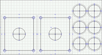
To start, I measured the control panel "face" (where the controls would end up being), and noted the dimensions. Next, using the mounting diagrams for the joysticks and buttons from the Happ Controls website, I created a to-scale template using Visio. After playing with a few different orientations, I came up with a pretty awkward arrangement of buttons - thinking that I needed to give the maximum amount of metal in between the button holes, for stability and clearance reasons. However, we quickly scrapped my first idea and went with the standard pattern you see below, it's much more "playable." 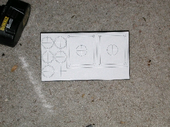 To me, it seemed like the drilling would be a little tight. I'd drawn in all the keepouts from the Happ Diagrams, but we were
really cramming a lot on these panels. (If you're drawing a similar template in Visio, make sure that when you place controls
on the top, that you're always taking into account the maximum keepout for each item. For instance, the pushbuttons are only 1"
around, but on the bottom where the plastic nuts secure them - you end up having to actually have about 1 1/4" each). I worried
that we were drilling holes to close, and either wouldn't be able to mount all the hardware, or would run the risk of ruining
the metal with too many holes. But, we decided to go ahead as planned with the new drilling template. We marked the centers
of all the holes with crosshairs, printed the template, and taped it down to the control panel.
To me, it seemed like the drilling would be a little tight. I'd drawn in all the keepouts from the Happ Diagrams, but we were
really cramming a lot on these panels. (If you're drawing a similar template in Visio, make sure that when you place controls
on the top, that you're always taking into account the maximum keepout for each item. For instance, the pushbuttons are only 1"
around, but on the bottom where the plastic nuts secure them - you end up having to actually have about 1 1/4" each). I worried
that we were drilling holes to close, and either wouldn't be able to mount all the hardware, or would run the risk of ruining
the metal with too many holes. But, we decided to go ahead as planned with the new drilling template. We marked the centers
of all the holes with crosshairs, printed the template, and taped it down to the control panel.
The actual drilling was the subject of much debate. When these things come pre-holed, they're actually stamped out at a metal shop - which gives much cleaner and accurate holes than just drilling would. Ideally, I wanted to use a 1" metal bit on a drill press, but since we were a little over-anxious - we decided to borrow a 1" hole-saw attachment for a hand drill and try that. I also dropped $29 on a 1" metal bit - which we tried on one pushbutton hole, and promptly gave up. In the end, the hole-saw ended up working fine. We drilled pilot holes 1st, to help guide the hole-saw and other bits. Since the seemingly long-ago days of my project, there are now some better options for control-panel drilling. The people at www.arcadedepot.com will sell you custom-drilled panels for a mere $25. Believe me, if your panel layout is relatively simple like mine - it's worth it. They also now offer a 3rd side-panel option for their cocktail cabs, which enables you to play horizontal as well as vertical games. The pushbutton mounting diagrams from Happ list the holes as needing to be something like 1.13" in diameter, and luckily the hole-saw makes a slightly larger hole than 1" - so it worked great. I also used the same bit for the joystick shaft holes, which in reality are supposed to be slightly larger - but the same size works just fine. I would still recommend a drill press for the best results, but we managed to do the whole thing with a cordless drill, putting the control panel over a block of wood and then clamping that whole assembly into a vise where we drilled out the holes. We went through a battery on the drill every 2 holes, so this took quite a while. Have someone with some oil or lubricant spritz the drill bit every few seconds to keep the whole thing from getting too hot. 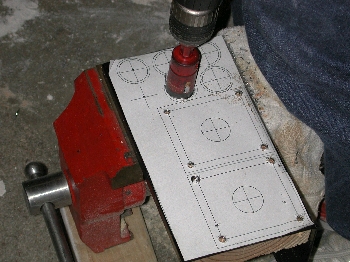
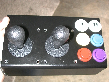
The joysticks need a total of 5 holes each. 4 to actually mount them (for this we used carriage bolts), and the center hole for the shaft. The Happ mounting diagram lists the mounting holes as needing to be about 1/4", but since we wanted to use 1/4" carriage bolts (smaller sizes aren't as easily found at the hardware store), we went 17/64" on them. This left room for the square part of the carriage bolt to clear the holes too. When it was all done, we did a test fit of the buttons - and we're very pleased. A warning though, take care not to scratch the black finish on the panels while drilling. In retrospect, it would probably have been wise to tape up the exposed metal, since we did get a few surface scratches from the vise clamping and over-zealous drilling. Looking at it now, I'm pretty sure we managed to get the maximum amount of usable buttons and joysticks on these little panels. I guess you could have mounted the player 1/2 start buttons above the joysticks and given each player 6 buttons - but I figured there were few cocktail-oriented games that required 6 buttons per player. And, this machine was going to be dedicated mainly to the older arcade games, many of which only used one or two buttons each. So 4 "fire" buttons per player seemed perfect. 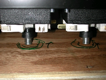 A test fit of the buttons and joys showed that our drilling was right on the money, but there were a couple problems that would
need fixing. Number one, the joystick shafts are too long! The problem here is that the original Pac-Man joys were pretty short
on the mounted underside. Happ sells the original "red-ball-on-top" Pac-Man joys, but I opted for the much cheaper "super"
joysticks - which can be configured as either 8-way or 4-way. One of the things that's great about Happ's super joys is that
they are highly flexible in how they can be used. They're able to go 4-way or 8-way, and they also have a couple different relief
cuts in the shaft so that you can snap the spring tensioner ring in at a couple different heights. This allows you to have a
joystick with a longer shaft (for wood mounting I assume), or shorter (for metal mounting). It's a great feature, but you get
about 1/2" more joystick shaft protruding on the bottom than you would from a Pac-Man joy. The problem is, the shafts were
butting up against the wood in the panel enclosure. The sticks wouldn't move, it looked like we needed about 1/4" "rut"
in the wood to accommodate unhindered movement of the joysticks.
A test fit of the buttons and joys showed that our drilling was right on the money, but there were a couple problems that would
need fixing. Number one, the joystick shafts are too long! The problem here is that the original Pac-Man joys were pretty short
on the mounted underside. Happ sells the original "red-ball-on-top" Pac-Man joys, but I opted for the much cheaper "super"
joysticks - which can be configured as either 8-way or 4-way. One of the things that's great about Happ's super joys is that
they are highly flexible in how they can be used. They're able to go 4-way or 8-way, and they also have a couple different relief
cuts in the shaft so that you can snap the spring tensioner ring in at a couple different heights. This allows you to have a
joystick with a longer shaft (for wood mounting I assume), or shorter (for metal mounting). It's a great feature, but you get
about 1/2" more joystick shaft protruding on the bottom than you would from a Pac-Man joy. The problem is, the shafts were
butting up against the wood in the panel enclosure. The sticks wouldn't move, it looked like we needed about 1/4" "rut"
in the wood to accommodate unhindered movement of the joysticks.
The next problem was with the joystick assemblies. Seems that our button keepouts on the diagram were not exactly right, and the rightmost joystick assembly was too close to the button fastener nuts. No problem there, we just used the Dremel to shave off the soft plastic mounting housing on the joystick. We also had to drill out the 4 mounting holes on each joystick, since they weren't big enough to accommodate our 1/4" carriage bolts. 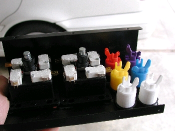
Next was the issue fitting all the microswitches onto the buttons and joys. We did have to do some creative positioning of all the �switches on the bottom, so that the terminals wouldn't run into each other. In the case of the player 1/2 start buttons, the switch terminals had to be pointed right at each other in order for the little men on the buttons to each be in the right orientation. We ended up having to bend the terminals on one of the �switches to make them both fit.  With everything screwed tight and bolted down, it was really starting to look impressive. With both panels done, it was time
to start thinking about wiring these things. Since the buttons and joysticks all work off simple off/on �switches, you only
have to connect 2 of the 3 terminals per switch. The ground sides can be daisy-chained together, and the "NO" sides each need
a line to the I-PAC. I set about getting some hookup wire from Radio Shack, and some "easy-crimp" style terminal attach thingies
from the auto parts store. The crimp-style terminal attach things worked great, but I wanted a sturdier connection - since,
should one get jarred loose, it would be a huge pain to get your hands up into the panels once the cabinet was fully assembled.
We decided that in addition to the crimped attachments, we would also solder each terminal to the switches. Soldering provided
a much stronger attachment, just what I was looking for. Beware! It takes a while to cut, strip and crimp wire to these panels.
But it must be done before you mount them to the cabinet! When you're done you'll have a rat's nest of wires - so it's not a bad
idea to label each one with some masking tape (unless of course you splurged and bought a bunch of multi-color hookup wire in the
1st place).
With everything screwed tight and bolted down, it was really starting to look impressive. With both panels done, it was time
to start thinking about wiring these things. Since the buttons and joysticks all work off simple off/on �switches, you only
have to connect 2 of the 3 terminals per switch. The ground sides can be daisy-chained together, and the "NO" sides each need
a line to the I-PAC. I set about getting some hookup wire from Radio Shack, and some "easy-crimp" style terminal attach thingies
from the auto parts store. The crimp-style terminal attach things worked great, but I wanted a sturdier connection - since,
should one get jarred loose, it would be a huge pain to get your hands up into the panels once the cabinet was fully assembled.
We decided that in addition to the crimped attachments, we would also solder each terminal to the switches. Soldering provided
a much stronger attachment, just what I was looking for. Beware! It takes a while to cut, strip and crimp wire to these panels.
But it must be done before you mount them to the cabinet! When you're done you'll have a rat's nest of wires - so it's not a bad
idea to label each one with some masking tape (unless of course you splurged and bought a bunch of multi-color hookup wire in the
1st place).
 When it came time to actually mount the wired and ready control panels to the cabinet, another realization was made. The
instructions from arcadedepot.com show a small piece of wood going along each side of the control panel to "stabilize" them
and aide in securing them to the inner cabinet. Problem was, we took up nearly the entire control panel with our buttons and
joysticks. These support pieces go in the control panel cavity area and kind of "shore up" the panels so they're not going
anywhere - especially getting knocked back into the cabinet if someone bangs on them too hard. They are also key in securing
the panel to the actual inner cabinet wall with a metal brace. Without these support pieces, our panel would be susceptible to
possibly being pushed back into the cabinet, and perhaps not be as well fastened to the inner cabinet wall as it should be.
When it came time to actually mount the wired and ready control panels to the cabinet, another realization was made. The
instructions from arcadedepot.com show a small piece of wood going along each side of the control panel to "stabilize" them
and aide in securing them to the inner cabinet. Problem was, we took up nearly the entire control panel with our buttons and
joysticks. These support pieces go in the control panel cavity area and kind of "shore up" the panels so they're not going
anywhere - especially getting knocked back into the cabinet if someone bangs on them too hard. They are also key in securing
the panel to the actual inner cabinet wall with a metal brace. Without these support pieces, our panel would be susceptible to
possibly being pushed back into the cabinet, and perhaps not be as well fastened to the inner cabinet wall as it should be.
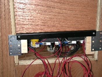 The solution the we came up with was to make as much of a "support" block as we could. We couldn't support the entire length
of the panel like the cabinet instructions recommended - but we could at least put some small support blocks that would give
us a tighter attachment to the inner cabinet wall. These were basically just hacked pieces of wood that allowed us to get the
stability we wanted.
And, it worked great for the panel without the player 1/2 start buttons. For the panel with the start buttons,
we had to get a little more creative - since cramming 6 buttons along the right side of the panel pretty much eliminated any room
we may have had to mount some sort of panel support.
The solution the we came up with was to make as much of a "support" block as we could. We couldn't support the entire length
of the panel like the cabinet instructions recommended - but we could at least put some small support blocks that would give
us a tighter attachment to the inner cabinet wall. These were basically just hacked pieces of wood that allowed us to get the
stability we wanted.
And, it worked great for the panel without the player 1/2 start buttons. For the panel with the start buttons,
we had to get a little more creative - since cramming 6 buttons along the right side of the panel pretty much eliminated any room
we may have had to mount some sort of panel support.
|
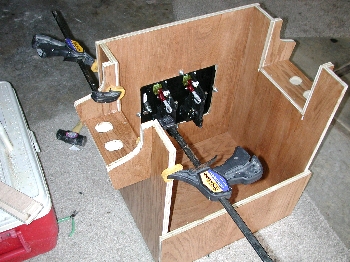
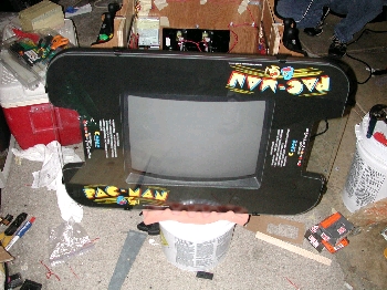
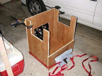 Following the assembly instructions that came with the cabinet, we began putting this beast together. The bulk of the cabinet
assembly is dead easy. Some wood glue and dowels, and you're good to go. The dimensions do present some problems when it comes
to clamping things together for tight glue drying. We actually used some nylon tie-downs to wrap around the square of the cabinet
and were able to effectively "clamp" all the sides that way. If you had the longer "screw" type wood clamps, or perhaps some corner
clamps - you could do it that way too.
Following the assembly instructions that came with the cabinet, we began putting this beast together. The bulk of the cabinet
assembly is dead easy. Some wood glue and dowels, and you're good to go. The dimensions do present some problems when it comes
to clamping things together for tight glue drying. We actually used some nylon tie-downs to wrap around the square of the cabinet
and were able to effectively "clamp" all the sides that way. If you had the longer "screw" type wood clamps, or perhaps some corner
clamps - you could do it that way too.
 Mounting the coindoor was also simple. Four holes to drill, and we used standard 1/4" carriage bolts. The coindoor cutout that
arcadedepot.com provides is cut for the standard Williams pinball type doors. Happ sells a Williams compatible coindoor that drops
right in without a problem.
Mounting the coindoor was also simple. Four holes to drill, and we used standard 1/4" carriage bolts. The coindoor cutout that
arcadedepot.com provides is cut for the standard Williams pinball type doors. Happ sells a Williams compatible coindoor that drops
right in without a problem.
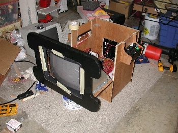
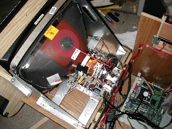
 The monitor mounting was a little tricky, but with some help from friends - we got it installed and mounted correctly. The
thing you need to keep in mind when mounting the monitor is that it's not made to fit in the display cutout with just default
mounting. You need to shim up the monitor on both the cabinet top and side to make it sit centered in the cabinet's top window,
and sit at the right hiegth enough to make the bezel do it's job (think of it as "standing off" from the cabinet top). Since
it's not as simple is bolting the monitor to the cabinet, some guesswork and trial and error type manuevering is required.
The monitor mounting was a little tricky, but with some help from friends - we got it installed and mounted correctly. The
thing you need to keep in mind when mounting the monitor is that it's not made to fit in the display cutout with just default
mounting. You need to shim up the monitor on both the cabinet top and side to make it sit centered in the cabinet's top window,
and sit at the right hiegth enough to make the bezel do it's job (think of it as "standing off" from the cabinet top). Since
it's not as simple is bolting the monitor to the cabinet, some guesswork and trial and error type manuevering is required.
 display cutout. Using this method we could adjust both the hiegth of the monitor relative to the hinged top, and the left/right
alignment as well. Once we were satisfied with the alignment with respect to the hinged door, we made sure the monitor was
pushed up close enough to the cabinet top, so the bezel was making slight contact with the CRT and doing it's job making the
unit look seamless. We then bolted the monitor to the hinged top, and measured some wood to make the right sized "stand offs"
for moutning it to the cabinet top. Once everything was adjusted, measured, and bolted - the monitor was securely in place
and aligned properly with the bezel cutout.
display cutout. Using this method we could adjust both the hiegth of the monitor relative to the hinged top, and the left/right
alignment as well. Once we were satisfied with the alignment with respect to the hinged door, we made sure the monitor was
pushed up close enough to the cabinet top, so the bezel was making slight contact with the CRT and doing it's job making the
unit look seamless. We then bolted the monitor to the hinged top, and measured some wood to make the right sized "stand offs"
for moutning it to the cabinet top. Once everything was adjusted, measured, and bolted - the monitor was securely in place
and aligned properly with the bezel cutout.
 lines up. The way we did it, we first fiddled with the shims and made sure the monitor was in the right position. Then we
removed the monitor and attached only the shim material to the cabinet. We then put the monitor back in place and attached
it to the shim material. After it was all done, we ended up mounting the monitor about 1 3/4" off the hinged side, and about
2" from the cabinet top (those aren't actual measurements, just eyeball guesses).
lines up. The way we did it, we first fiddled with the shims and made sure the monitor was in the right position. Then we
removed the monitor and attached only the shim material to the cabinet. We then put the monitor back in place and attached
it to the shim material. After it was all done, we ended up mounting the monitor about 1 3/4" off the hinged side, and about
2" from the cabinet top (those aren't actual measurements, just eyeball guesses).
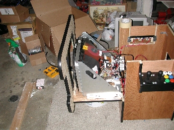
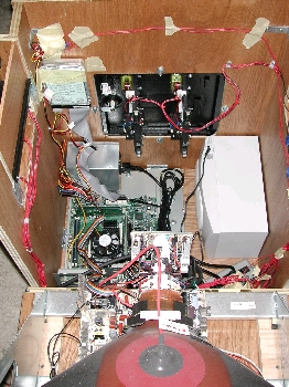
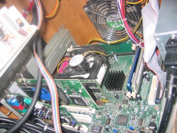
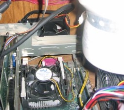
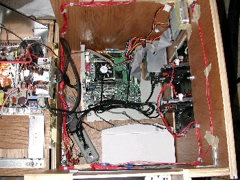 After the cabinet was fully assembled, it came time to begin mounting the various components that would make up the brains and
guts of the machine. First off, the motherboard was fitted to the bottom. No special work was required here. I mounted to
motherboard on a case insert from a chassis for an old PC. The one I found was perfect because it has the I/O sheild and
back-panel card moutning slots attached as one solid piece. This was a big help to me since I could secure the PCI and AGP
cards to the metal and not worry about them coming unseated or being subject to movement. Luckily, the whole board fit in the
bottom of the case, and even with a litte cut-away where I could mount the power supply. I used two of the pre-drilled holes
in the board mount to attach the whole mess to the bottom of the cabinet. With that done, I used some industrial strength velcro
to fix the power supply to the botttom of the case, next to the board (making sure all the needed power connectors could reach
their plugs on the board). Make sure your power supply has enough room to get sufficient ventilation. Don't put the intake or
exhuast end of the fan right against the wall of the case, or any other obstacle. The power supply needs a constant draw of
fresh air across it to keep it cool, so you need both intake and exhuast fans to have some space around them.
After the cabinet was fully assembled, it came time to begin mounting the various components that would make up the brains and
guts of the machine. First off, the motherboard was fitted to the bottom. No special work was required here. I mounted to
motherboard on a case insert from a chassis for an old PC. The one I found was perfect because it has the I/O sheild and
back-panel card moutning slots attached as one solid piece. This was a big help to me since I could secure the PCI and AGP
cards to the metal and not worry about them coming unseated or being subject to movement. Luckily, the whole board fit in the
bottom of the case, and even with a litte cut-away where I could mount the power supply. I used two of the pre-drilled holes
in the board mount to attach the whole mess to the bottom of the cabinet. With that done, I used some industrial strength velcro
to fix the power supply to the botttom of the case, next to the board (making sure all the needed power connectors could reach
their plugs on the board). Make sure your power supply has enough room to get sufficient ventilation. Don't put the intake or
exhuast end of the fan right against the wall of the case, or any other obstacle. The power supply needs a constant draw of
fresh air across it to keep it cool, so you need both intake and exhuast fans to have some space around them.
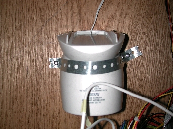 Next, I mounted the subwoofer to the oppposite side of the cabinet base. The only thing to keep in mind here is that I'd like
the controls and AC plug to be accessible - so that determined how I mounted the sub. Once I figured out how I wanted it and
where it would go, I used some more velcro to mount it to the side and bottom of the case. The right and left sattelites
speakers were mounted under the control panels on each side. I bought some cheap 1980's looking speaker covers from Radio
Shack (I think they had actually probably been in Radio Shack since 1980, and they were the last two they had). They lookes
totally authentic to the 1980's theme of the cabinet. I didn't want to drill huge holes for the speakers, mainly since I only
had a 1" holesaw available to me. So I just drilled a couple staggered 1" holes for each speaker, and mounted the speaker
grilles/covers over those. It was plenty of room for those little speakers to get their sound out of. For the speaker that
would get mounted above the subwoofer, I figured it would be easiest to just velcro it down to the subwoofer itself. That way
I didn't have to worry about fixing it to the cabinet wall, and I let it decide the heigth of where each speaker would be - and
mounted the opposite side to match up. This worked out great because the speaker that I mounted directly to the subwoofer
(with velcro again), has the volume controls and power button. So if I ever want to manually adjust the volume or turn off
the speakers - I can simply un-velcro the speaker and use the controls, something I coudn't do if it was hard-mounted to the
case. For the other speaker, I simply mounted it directly to the side of the cabinet, in-line with the drilled holes. To fix
it, I stretched some plumber's tape around it and screwed it down on either side. I mounted it upside-down since it would prevent
if from sliding out of the mounting tape. Once the speakers were mounted, I just cleaned up the wiring and plugged them into
the sound card.
Next, I mounted the subwoofer to the oppposite side of the cabinet base. The only thing to keep in mind here is that I'd like
the controls and AC plug to be accessible - so that determined how I mounted the sub. Once I figured out how I wanted it and
where it would go, I used some more velcro to mount it to the side and bottom of the case. The right and left sattelites
speakers were mounted under the control panels on each side. I bought some cheap 1980's looking speaker covers from Radio
Shack (I think they had actually probably been in Radio Shack since 1980, and they were the last two they had). They lookes
totally authentic to the 1980's theme of the cabinet. I didn't want to drill huge holes for the speakers, mainly since I only
had a 1" holesaw available to me. So I just drilled a couple staggered 1" holes for each speaker, and mounted the speaker
grilles/covers over those. It was plenty of room for those little speakers to get their sound out of. For the speaker that
would get mounted above the subwoofer, I figured it would be easiest to just velcro it down to the subwoofer itself. That way
I didn't have to worry about fixing it to the cabinet wall, and I let it decide the heigth of where each speaker would be - and
mounted the opposite side to match up. This worked out great because the speaker that I mounted directly to the subwoofer
(with velcro again), has the volume controls and power button. So if I ever want to manually adjust the volume or turn off
the speakers - I can simply un-velcro the speaker and use the controls, something I coudn't do if it was hard-mounted to the
case. For the other speaker, I simply mounted it directly to the side of the cabinet, in-line with the drilled holes. To fix
it, I stretched some plumber's tape around it and screwed it down on either side. I mounted it upside-down since it would prevent
if from sliding out of the mounting tape. Once the speakers were mounted, I just cleaned up the wiring and plugged them into
the sound card.
 With everything assembled and running, things seemed to be working splendidly. However, it soon became apparent that there were
going to have to be some changes. The first day I had the machine back in my apartment, I ran it all day as a test. The machine
worked great, the games and controls worked as expected - but there was a problem. When I got home and checked the cabinet, the
carriage bolts on the coindoor were warm to the touch - on the outside of the cabinet! I quickly opened the coindoor and stuck
my hand inside to feel the temperature. You wouldn't believe how hot it had got inside that wooden box. Now, all PCs have fans
to induce airflow inside the chassis, most having an intake and exhuast that try to blow air across the CPU, memory, and voltage
regulator components (the hottest operating parts of the board). Not only did the cabinet have zero airlfow - it also contained
a 19" CRT adding to the ambient temperature, as well as the power supply which was getting constatnly recycled hot air. The
temperature inside the cabinet was unhealthy for the PC and other parts, and I knew I'd have to do something to fix it.
With everything assembled and running, things seemed to be working splendidly. However, it soon became apparent that there were
going to have to be some changes. The first day I had the machine back in my apartment, I ran it all day as a test. The machine
worked great, the games and controls worked as expected - but there was a problem. When I got home and checked the cabinet, the
carriage bolts on the coindoor were warm to the touch - on the outside of the cabinet! I quickly opened the coindoor and stuck
my hand inside to feel the temperature. You wouldn't believe how hot it had got inside that wooden box. Now, all PCs have fans
to induce airflow inside the chassis, most having an intake and exhuast that try to blow air across the CPU, memory, and voltage
regulator components (the hottest operating parts of the board). Not only did the cabinet have zero airlfow - it also contained
a 19" CRT adding to the ambient temperature, as well as the power supply which was getting constatnly recycled hot air. The
temperature inside the cabinet was unhealthy for the PC and other parts, and I knew I'd have to do something to fix it.
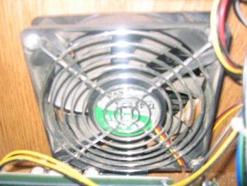
 wouldn't get acidentally drilled, and to get inside and mount the fans. Once the holes were drilled, I mounted the fans on the
inside of the case (one as an intake and one as exhaust), and mounted all the components back into place. Later on I will cover
the fan holes with round speaker grilles (like for the 5" car stereo speakers), but for now they are rough-drilled holes in the
case for testing purposes.
wouldn't get acidentally drilled, and to get inside and mount the fans. Once the holes were drilled, I mounted the fans on the
inside of the case (one as an intake and one as exhaust), and mounted all the components back into place. Later on I will cover
the fan holes with round speaker grilles (like for the 5" car stereo speakers), but for now they are rough-drilled holes in the
case for testing purposes.